Chip S
Active Member
- Jun 17, 2019
- 432
- Boat Info
- 1993 Sea Ray 200 Overnighter
- Engines
- 2023 Mercury 150 hp Four Stroke Outboard
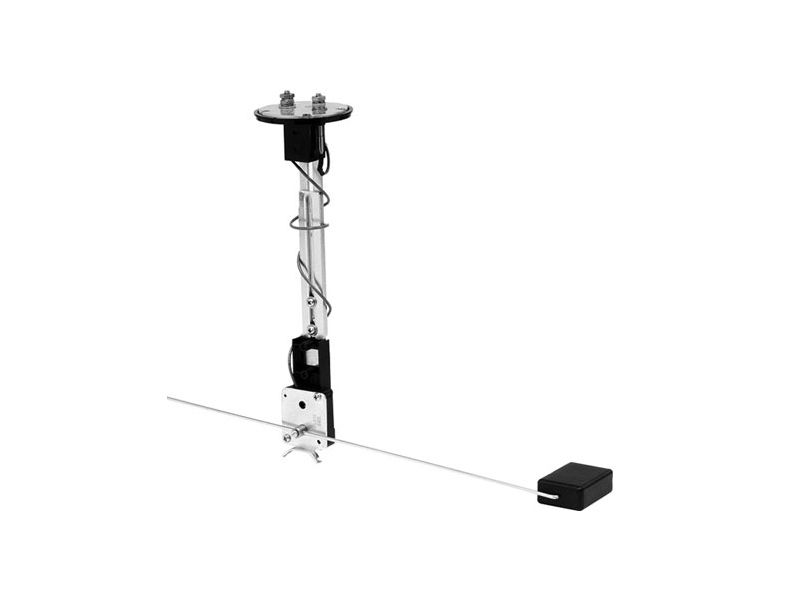
Does anyone know the fuel gauge ohm values Sea Ray was using in 1993? The PO had the fuel sender replaced with an American Standard sender (Full = 33.5 ohms, Mid = 103 ohms, Empty = 240 ohms). I measured the ohm values at the sender. Full measured at 33 ohms. 60% Full measured at 90 ohms. My guess would be that 50% Full would be around 103 ohms, which is what it should be.
The gauge is reading Full at 33 ohms. The gauge is reading 12% Full (1/8) at 90 ohms (not 60% Full). It seems like the gauge is working but is using a different resistance standard. With the current situation, my gauge reading of Empty is equal to half a tank remaining and my gauge reading of Full is equal to a full tank.
The gauge is reading Full at 33 ohms. The gauge is reading 12% Full (1/8) at 90 ohms (not 60% Full). It seems like the gauge is working but is using a different resistance standard. With the current situation, my gauge reading of Empty is equal to half a tank remaining and my gauge reading of Full is equal to a full tank.
") If you can peg the needle back and forth from the pink wire at the sender, then the wiring and the gauge are good. Diagnostics are done. Replace the sender.
If you can peg the needle back and forth from the pink wire at the sender, then the wiring and the gauge are good. Diagnostics are done. Replace the sender.