KMAS100
Member
Hi folks,
Can anyone help please…..
I have a 1990 420da with 3208ta 375hp engines. The local caterpillar mechanic here (in Cyprus) has had both engines out along with the gearboxes and overhauled both sets of units. A great job and good work!
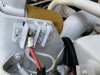
However… his helper that assisted in disconnecting the wiring didn’t take note of the alternator connectivity and also threw away ‘a tacked-on bulb’ setup. So we now have no idea what connectivity goes to what on the alternator and where the bulb connected to or even what it was for?
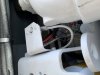
Here’s what we have…
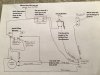
1) Thick red wire coming from the battery isolator
2) Thick black wire coming from the starter
3) Yellow/Green coming from the fuel cut-off
4) Orange wire coming from a cut-off switch
5) Red wire coming from a block connector
The light bulb?.. is this to excite the alternator? How should it be connected and what wattage should it be? Anything else connected to this?
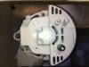
The alternator is a Prestoline. I’ll try and upload an identical picture I’ve found on the internet
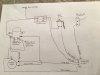
Can anyone please advise which wires connect to which terminals and the use and connectivity of a bulb setup?…
Can anyone help please…..
I have a 1990 420da with 3208ta 375hp engines. The local caterpillar mechanic here (in Cyprus) has had both engines out along with the gearboxes and overhauled both sets of units. A great job and good work!
However… his helper that assisted in disconnecting the wiring didn’t take note of the alternator connectivity and also threw away ‘a tacked-on bulb’ setup. So we now have no idea what connectivity goes to what on the alternator and where the bulb connected to or even what it was for?
Here’s what we have…
1) Thick red wire coming from the battery isolator
2) Thick black wire coming from the starter
3) Yellow/Green coming from the fuel cut-off
4) Orange wire coming from a cut-off switch
5) Red wire coming from a block connector
The light bulb?.. is this to excite the alternator? How should it be connected and what wattage should it be? Anything else connected to this?
The alternator is a Prestoline. I’ll try and upload an identical picture I’ve found on the internet
Can anyone please advise which wires connect to which terminals and the use and connectivity of a bulb setup?…