Replacing Cool Fuel III

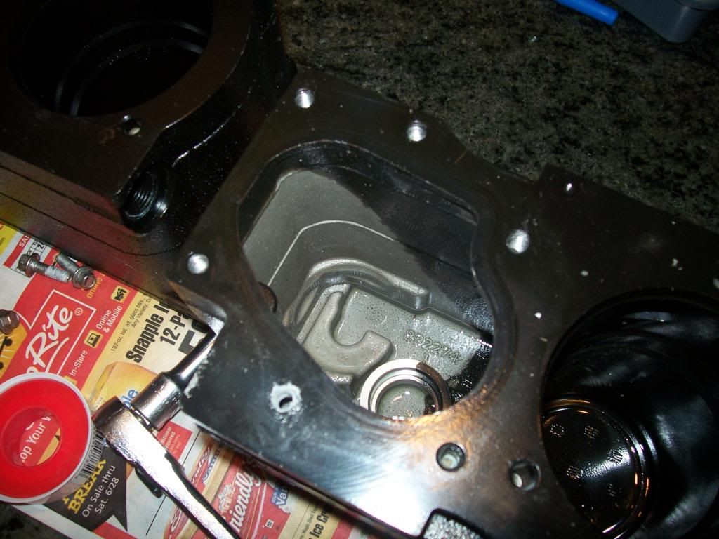
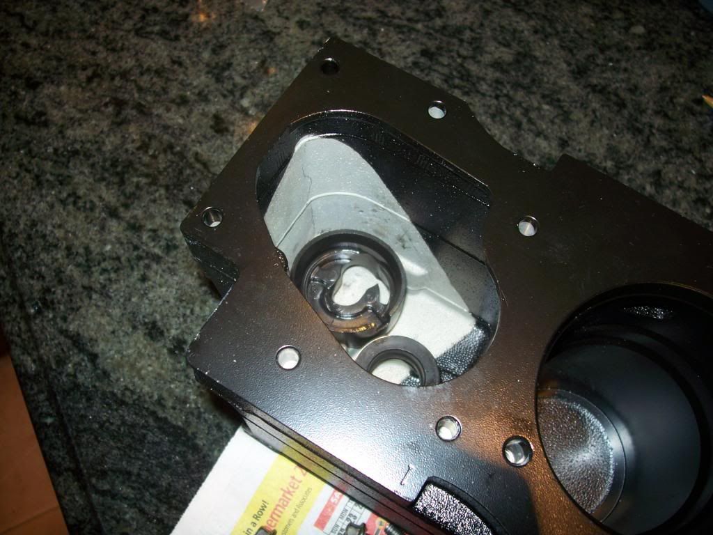
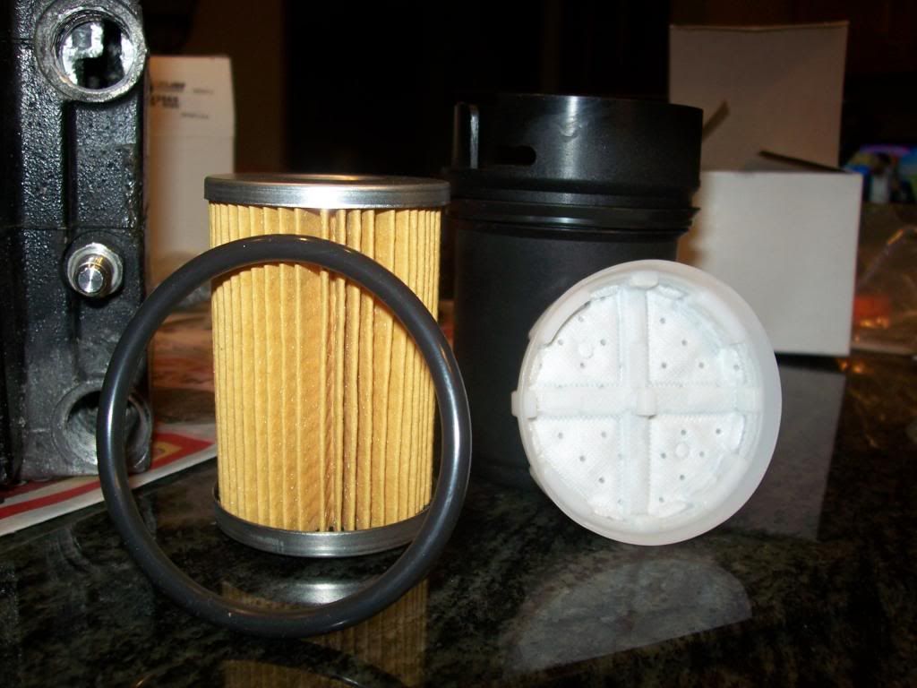
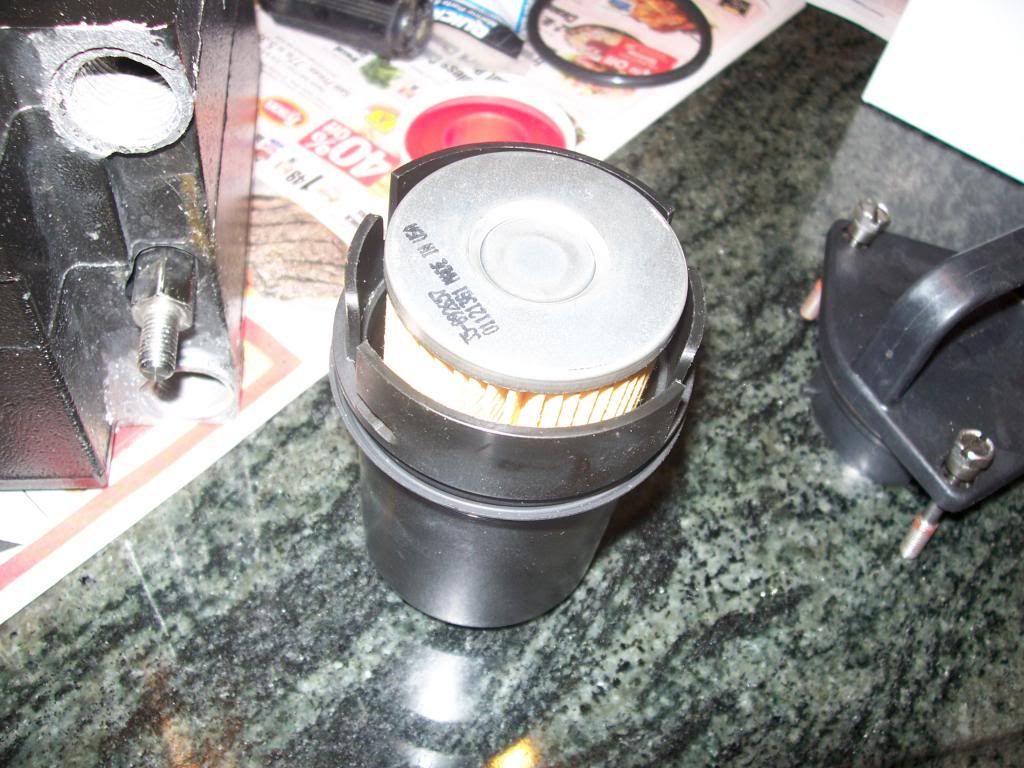
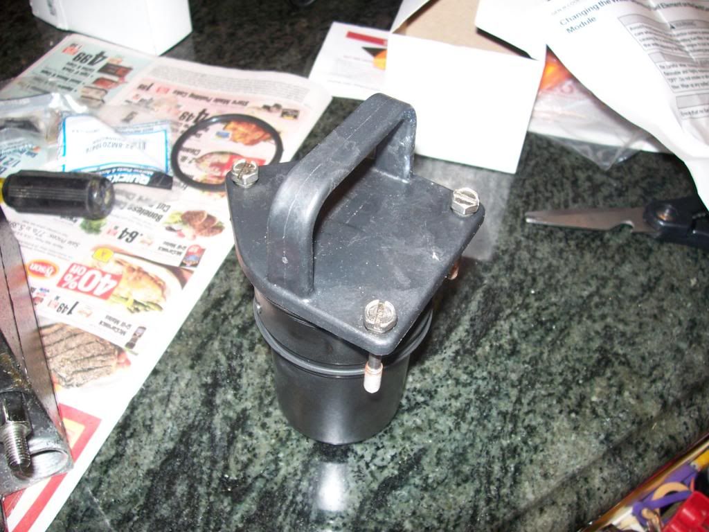
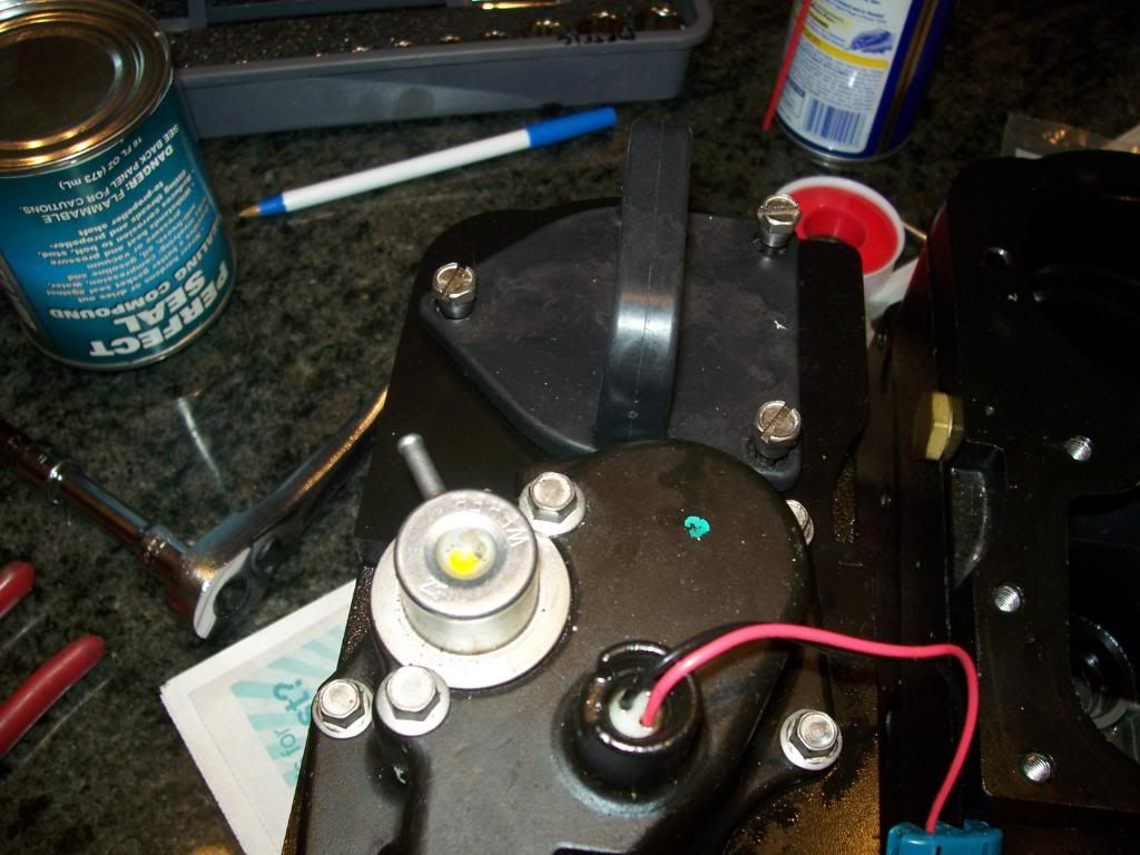
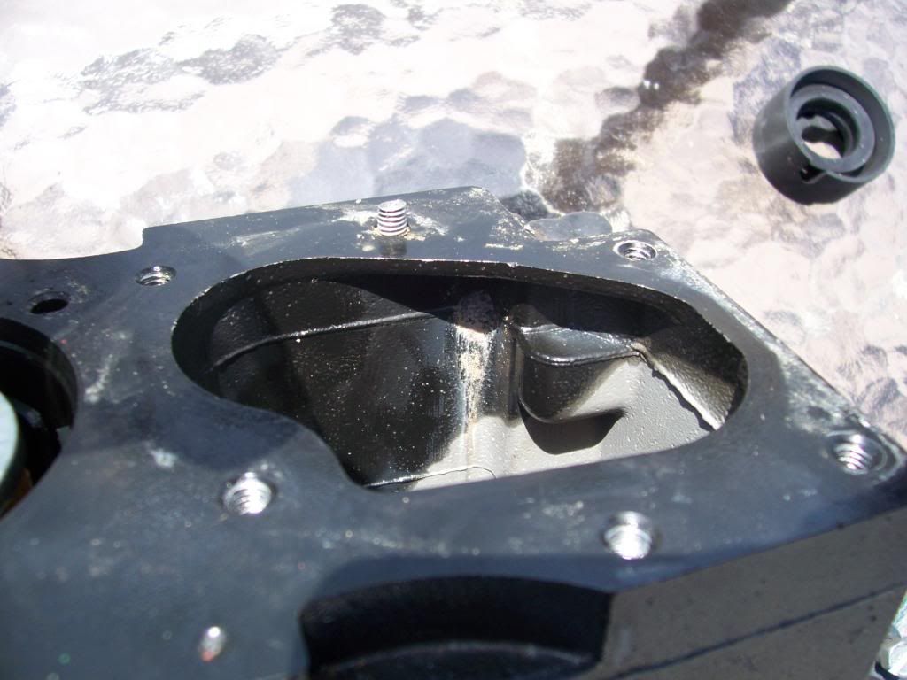
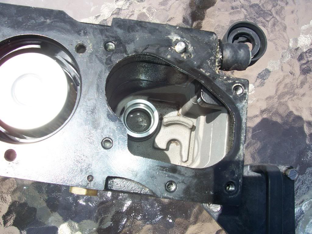
Good write up Ron. My cousin has a 320 and just learned one of his Cool Fuel III units has failed and it's recommended to replace both of them. I'm sending him this link.

Go clean your bilge.
 
Nehalennia - Do you have any sense on your cousins boat whether it was in an area that only has e10 fuel to run. How much salt water has it been in. It would be nice to get some commonality on what causes the failures of these units. I am in an area that is freshwater and e10 is everywhere. But I never hear of any failures in my area.
 
It is run in saltwater 99% of the time and returns to port in brackish water. He moors in Everett, WA, 25 miles North of Seattle. Everett is on Puget Sound (saltwater). Twice a year, we'll run the boats South and into Lake Washington in Seattle. The fuel dock he typically fuels at does not have E10 fuel. I would think that in freshwater, as you are, that the corrosion issues would be minimal.
 
So, my old CF3 unit was perforated and not even good as a spare. So I can't go with the machining modification. Therefore, according to UPS tracking, this is going to arrive on my doorstep today...

ITEM 1


44814.png


It's OEM and it is CF4, and it is sold separately. All problems with CF3 are in relation to item 1 in the diagram. The pumps and filter are the same for CF3 and 4 - mine work and they are have nothing to do with the issues that plague CF3. So there is no reason to buy the entire $900 item, which is what I did on the starboard engine. The port side seems fine; but if one is shot, it's likely the other one is sure to follow.


BTW, the "new" CF4 is identical to my old CF3 OTHER THAN the different fittings (item 2) and the blue wingnut water drain (item 3). The insides are painted, just like mine. And the casting is aluminum and can corrode galvanically and perforate, just like mine. So all you CF4 people out there need to keep an eye on things as well. You don't actually think Merc would make improvements that solve all problems, do you? I only knew mine needed investigation b/c the water line in was dripping slightly into the bilge (another reason to keep a dry bilge).


What is also important to understand is that this is purely a problem with the water lines. There are no issues with the fuel lines "in" and "out," nor are these modified by machining the old units. The worst thing that happens here is that the old water fittings leak into the bilge or, if perforation goes undetected, seawater will get into your fuel, which could foul the injectors and leave you dead in the water with a big repair bill.
 
Last edited:
Pulled the old CF3 on the port engine today. Zero evidence of paint flaking. Matter of fact, looks like the same robot that painted the one I took out painted the new one...

OLD ONE
106_4930_zps06518a2a.jpg


NEW ONE
106_4931_zpsa9cdf7e2.jpg


The new housing doesn't come with the filter holder or the filters. I had ordered these parts as spares last year.
106_4933_zpsa733a240.jpg


First you shove in the disk filter...
106_4934_zpsf3e3934d.jpg


Then put the paper cartridge filter ($35 for this piece of crap) into the handy dandy filter holder...

106_4935_zpsa0fd1a8d.jpg


Put the twist-lok carrying handle on...
106_4936_zps7a9411e6.jpg


and bolt it down to the new unit. In this picture, the old pump module (the thing with the wires) has already been installed..

106_4937_zpsfce60b0a.jpg


Examination of the old CF unit reveals corrosion in the upper right corner, which also managed to corrode the nearest fastener. Note that the head broke off when I was trying to get it out...

106_4939_zpsa6ca549b.jpg


Here you can see the broken bolt in the 12 o'clock position and if you look carefully you will see little pieces of corroded metal at the bottom of the unit.
106_4938_zpscfe07792.jpg


Just to the right of the broken bolt head is the raw water connection. Note the "crud" around the fitting. I don't know if the "new" fittings will solve this problem. The fittings are plastic, as are the new ones. So this is probably not galvanic corrosion. Maybe they just leaked and that's what caused the problem?? This fittings on this unit were not leaking into the bilge when I replaced it - the starboard engine was. But I would caution anyone with CF3 or CF4 to check these fittings. Much like exhaust mainfolds (which are also jacketed castings), if they are cruddy on the outside, they are likely cruddy on the inside.


On a side note, I could not get this engine started after I reinstalled all this stuff. I cycled the pump with the ignition switch many times before trying to start (which would typically fill the chambers with gas). Still wouldn't start, though I could hear the pump running. Took the filter module out and the chamber was bone dry. Gave Dale MasterFab a call and he suggested it may need a dose of fuel poured in to get the pump primed. I had no fuel handy so I packed it in and went home. Will go back tomorrow with a small container of gasoline and try again.
 
Last edited:
Bleed the air out with your pressure tester on the fuel rail. Flaking paint is only in/under the pressure regulator on the cover. Have you looked at it?
 
Pressure tester?
 
Fuel pressure tester, you should have 1 on there anyway just to see where your at. That's how I figured out I had the paint issue, when my pressure was at 70#'s. There's a button on the side of the tool to bleed of pressure. Don't forget to open your gas valve. Also, pull that regulator off and have a peek
 
Another 5 hours of futile labor today and could not get fuel to flow INTO the new CF unit. Verified that there is fuel TO the unit. Got the engine to run if I pre-loaded the unit with fuel but it dies when the few ounces the CF holds is burnt off. Bench tested each of the pumps - they both work with 12v applied directly. Only thing I can think of is that one of the rubber bushings that aligns the hi pressure pump into the housing is not ... aligning properly. Maybe closing off an orefice. You can't see what's going on in there once you drop the pump assembly into the housing. So it entails re-installing everythingn(including one 4" exhaust hose" and testing to see if fuel gets into the housing. I did this 4 times after trying disassembling the pumps and very carefully reassembling. Just won't work. So I give up.

Just ordered an entire NEW CF4 unit to the tune of $857.94. When I installed an entirely new unit on the other engine all went perfectly. I could mess with this longer than the 10 hours I now have invested but I'm choosing not to!

My theory is that the rubber bushing (item 16 in post #44 above) is not aligning properly and cutting off the suction. But I don't know this for sure. All I know is that each time I take things apart to try re-assembling again, the bushing seems slightly crimped, as if it went in misaligned. Whatever. I am a gracious loser and can admit defeat.

Anyone want to buy a barely used CF4 housing?? LOL
 
Just wondering. Would it at all be feasible/reasonable to retrofit/replace a CFIII integrated system with the separate parts of the Cool Fuel II system?
 
For anyone else interested in assembling the pumps in the module. Item #16, rubber bushing, has to fit perfectly clocked on the base of the high pressure pump. I found the best way to do this is to assemble both pumps into the cover and apply grease to #16 to hold it in place on the pump.and then screw the cover down to the module. The low pressure pump is self priming, so no need to add fuel . Prime the pump several times with the rocker switch at the helm. Bleed air out of the fuel rail if needed. 1 of my engines needed bleeding, 1 didn't.
 
Item #16, rubber bushing, has to fit perfectly clocked on the base of the high pressure pump.

I don't know the answer to that question.

Item #16, rubber bushing, has to fit perfectly clocked on the base of the high pressure pump.

Amen to that. I was afraid to use grease. It doesn't muck up the injectors? The pump with item #16...what role does it play? Is it drawing from the tank or is it sending fuel to the rail?
 
Manual #40

Gave this a look.

top of Page 27: Lo pressure pump, bottom grommet, which is called the "inlet seal" is recommended to be put into the housing. Got that. No problem. It is round and has no indexing at all. That thing was the easy part.


bottom of pate 26: The bottom grommet for the hi pressure pump, which is called an "isolator" is recommended to be put ONTO the pump, not onto the housing. No mention how to get it to stay on there though.

Scof...did you reuse the "isolator" that came out of your CF or did you buy a new one? I wondering if mine kept falling off and going in wrong b/c it was the old one and had become stretched out which would not allow it to fit snugly on the hi-pressure pump.

Also, I now see what you mean by the pressure regulator (item 10 in the diagram above). I didn't look at that thing at all. It was functioning fine on the both engines before I started this process so I figured it was still working properly. AND I tried swapping both sets of pumps into the housing and neither worked. Would be ironic if that is indeed the problem.

 
Last edited:
Ron, I did use my original #16 bushing,the isolator, it will not stay on the pump inverted, that's why I stuck it on with grease. Def. look at your pressure reg. 2 screws, that's where the paint collects
 
Let's say there's no paint there - what could go wrong with this regulator? Is it possible that it is preventing the hi press pump from drawing from the tank? I'm getting fuel at the rail if I pre-load the filter reservoir with fuel so it is able to draw from the filter side. Puzzling why it won't draw from the fuel line.
 
The regulator is probably not your problem if it was working previously. Low pressure pump fills the module. High pressure pump feeds the engine. Why did you take it apart in the first place? I'll tell you 1 thing Ron, you get an A+ for taking pix and posting them.
 
I took the pump module (that's the thing that pulls out when you remove the 6 bolts) out of the old CF3 in order to install it into the new CF4 case that I purchased. That was the whole point. I didn't actually dissect the pumps until the thing proved to not work, and even then I only dissected it to put 12v to each pump individually and see if they were both working, which they were (actually, I put voltage on all 4 pumps that came out of the 2 now deceased CF3 units, and they all worked).

My CF3 cases (both of them) were corroded through so I was not going to re-use them. I replaced the one on the starboard engine (which was leaking at the old fittings) with an entire new CF4 unit. That was plug-n-play and worked perfectly. Both my CF3s were working perfectly but were showing signs of imminent failure. And b/c they were working, the plan was to put the pumps and the filter module into a new CF4 housing, install it on the port engine and go boating. The housing is $387 compared to a $857 full CF4 unit. Didn't work out the way I envisioned. The mystery is "WHY didn't the plan work?"
 
Just wondering. Would it at all be feasible/reasonable to retrofit/replace a CFIII integrated system with the separate parts of the Cool Fuel II system?

Ron,

I'm with Bill on this one. I never had any vapor lock problems with my CFII on my 340 - and it was a lot simpler...and no paint flaking problems...
 
Been thinking a lot about this and the only thing I can think of is that the vacuum seal of the entire CF unit was not intact. Maybe the rubber gasket that seals the pump module in is flattened (I did not replace it) or the large O-ring that seals the filter chamber was not sealing properly. But I doubt that. These gaskets were still in very good shape.

I am still unclear as to what the pressure regulator does. There is a little rubber hose that slips over the spout of it and disappears somewhere into the underside of the motor (no idea where it goes - never looked). That hose doesn't carry fuel - it's maybe 1/8" in diameter and is merely slipped on - no clamps. Does it carry fuel vapors??? If it does maybe it allows air flow through, bu tonly in the OUT direction. If that's true and it is some sort of check valve which is stuck, maybe it's allowing air IN as suction is created by the low pressure pump, thereby messing up the pumps ability to draw fuel in from the tank.

Remember - when the pump is immersed in fuel by me filling it up manually, the engine runs. Once that few ounces of fuel burns off it shuts down b/c now maybe it's sucking air (??)
 

Forum statistics

Threads
113,163
Messages
1,427,604
Members
61,073
Latest member
kolak3
Back
Top