LClifton
Member
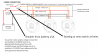
The plan is to follow SKybolt’s instruction. First is 10 gauge from battery to buss.The red and black need to be of a gauge to carry the anticipated current which should be 25 amps (the circuit breaker size).
The orange is a low current switch leg and can be 16 Gauge routed to the on and off switch. The switch leg would probably use a 5 amp circuit breaker or whatever suitable for the wire gauge and length.
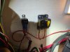
Positive side will be battery to breaker to buss. Negative side will be battery to buss also with 10 gauge. The pigtails from the lights will be extended as necessary with 14 gauge to buss. All inside a waterproof box. Properly wiring the orange to the switch is my next mental roadblock.
Last edited:
")