320DA Srtbrd Electrical SWPAD Module Question

Alex F

Well-Known Member
Nov 14, 2006
9,166
Miami / Ft Lauderdale
Boat Info
2005 420DB with AB 11 DLX Tender, Raymarine Electronics (2x12" MFDs) with Vesper AIS
Engines
Cummins 450Cs, 9KW Onan Generator, 40HP Yamaha for tender.
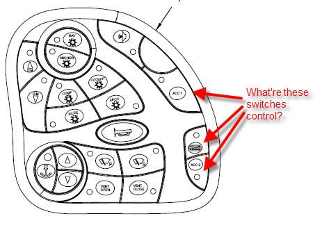
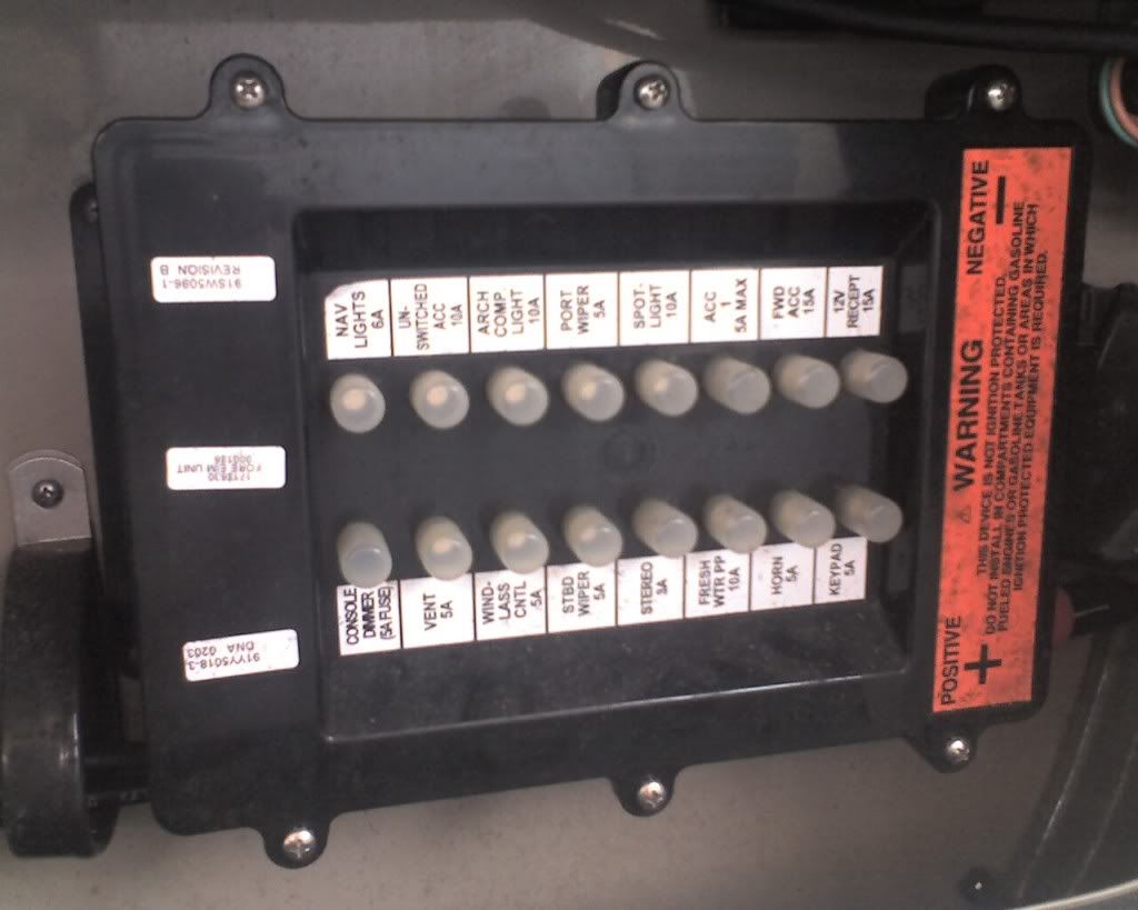
Do you guys have these switches controlling anything or they just reserved for additional and optional installations?

Strbrd_Module_Switches.jpg
 
Answered in 320 thread.

I had posted the question in Electrical Section, but I'll try here as well. Do you guys have these swithces control anything?

Strbrd_Module_Switches.jpg

Top - Nothing. On my boat, I wired it to the stereo remote back lighting.

Middle - It's the water pump switch, I think. I don't think it's operational on our boats.

Bottom - Nothing. On my boat, I wired it to the cockpit tv.
 
Answered in 320 thread.


Top - Nothing. On my boat, I wired it to the stereo remote back lighting.

Middle - It's the water pump switch, I think. I don't think it's operational on our boats.

Bottom - Nothing. On my boat, I wired it to the cockpit tv.

Thanks John,

I could see how top and bottom ones are labeled ACC1 and ACC2, which could mean they're just reserved. But, the middle one has image of what it looks like switch for water pump. I never used it, b/c we have dedicated switch/breaker on the main 12v control panel.

So, this means that we have all 3 switches reserved for additional installation.

Did you hard wired your 12v cockpit tv to this water pump switch?

12v_Control_Panel.jpg
 
Last edited:
This is a case of Sea Ray using one part across different models. That same switch pad is used on the 280DA (pre-'10). The box with the squiggly line is for the water pump on the 280.

280s don't have windshield vents, or port side wipers, but we have the switches on the switchpad!

The switches are functional, so you can use them for other stuff if you want. All you need to do is look at the wiring diagram and get the wire color and the pin out number on the EIM plug. Then go find the EIM and pull out the wire. On the 280 that switch is paired with an EIM located in the helm area.

Henry
 
So, this means that we have all 3 switches reserved for additional installation.

I have 4 not including the water pump switch. The two in your original post, above and below the water pump, then the "Aft Accy" and "Fwd Accy" on the other pad, if I remember correctly.
 
Thanks John and Henry for clarification.

So, this means I have total 5 free switches, including the water pump switch (3 on srbrd pad and 2 on port pad). This makes it easier to plan future mods.
 
Guys,

I just installed ST60 unit and need to hook it up to one of the switches to have ON/OFF capabilities for the unit. I'm thinking that "water pump" is a good candidate. Could you please suggest what's the best way to connect to the switch (I mean where's the wire ends so I can easely get to it to make the connections)? I don't have the diagram with me, so I don't know where these wires lead to.

Thanks,
Alex.
 
Assuming the 320 EIM is the same as the 280's pin number 20 should be ACC 1 and # 1 is water pump. Both are red with violet stripe. If you have good eyes, or a magnifying glass, the wires are imprinted with the circuit name. Look for this marking as all of the power wires seem to red/violet (according to wiring diagram).

The EIM on the 280 for the strbd switch is mounted up at the helm. You should be able to find it as it also contains the breakers for the things controlled by the switchpad.

Henry
 
Henry,

So does it mean that the wire goes from the panel to the switch pad and stops, so I'll need to run a wire from the switch to my ST60? Or another words, the switch has input coming from the panel, would you agree that the output from the switch is blank or does it lead to anywhere?
 
I installed my electronic compass so that power was controlled by a portside accessory switch on my 280. This is accomplished by following the harness from the forward Electronic Interface Module (EIM) and locating the correct wire as mentioned by Henry. You do not touch the switchpad itself. In order to locate the wire I had to remove the EIM and pull out the slack portion of the harness. The wire was bundled into the harness but was terminated in the bundle. I have no idea if the 320 will be the same, but I would guess it would be similar.

I used a meter to determine which switch was controlling the terminated wire once I found it. I was surprised to realize that a portside switch controlled a wire from the forward EIM, but that was the case.

The only other concern is to be sure that the amperage of the circuit is at least adequate (and use an inline fuse of the correct size if the circuit amperage is higher than required).
 
Thanks Bport. I'll try to find it next weekend. The amps are the least of my worry, ST60 uses about 2amps Raymarine techs told me.
 
on my 02 dancer the middle switch is for engine compartment heater which is between the engines heater

My guess is that they did what we did - research to find an unused switch, confirm the amperage of the circuit, find the wire's dead end, hook it up, then return the ground connection to the block serving that bundle.
 
Alex,

The wire coming from the EIM will be +, controlled by the switch on the pad, and protected by a breaker. All you have to do is hook the ST60 to that and then connect the ST60 - to ground.

Henry
 
Guys,

Please help me out with more details. I'm puzzled how these EIMs and switchpads work. The confusing part is that there are only 4 wires going to the switchpad while it has many more switches. So, it's not like usual two wires for one switch.

Here are the pictures of whaht I understant components involved:

View from behind the switchpad.
Photo_043010_008.jpg


This is where the the 4 wires go to (I'm guessing the EIM?)
Photo_043010_005.jpg


The breakers panel:
Photo_043010_004.jpg


According to diagram I'm looking at 4 wires:
252B red
253B blk
256B orn
257B grn

I was expecting to see a plug with terminated wires coming out of EIM, but I don't see them. I even tried the matching method by counting the existing wires going the EIM (3 plugs 11 total wires) the switch pad has lots more, so I can't make sense out of this yet.

Any ideas how to find a wire from any of 3 swithces (water pump, acc1 or acc2)?

Thanks,
Alex.
 
My apologies to those of you know the technology. From a functional standpoint, my observation is the EIM seems to be some kind of processing unit. The switches on the pads only seem to be communicating with the EIM. Basically you press a switch and the pad sends an ID to the EIM. The EIM then reads that and trips the relay associated with that ID. How this communication works, or what form the ID is, don't know.

You can see how enticing this technology might be. Simplified dash and control wiring. Its a pity these things can be so unreliable sometimes.

Henry
 
Unreliable switchpads and/or EIM. Mine just went out two days ago. My waterpump kept showing intermittent on and off on the switch pad. My batteries were drained to nothing and I called my mechanics. They said that (for an 04 sundancer) the switch pad was 300 bucks, the EIM was 500 bucks, and there's no way to test what failed (pad or EIM) so you have to gamble. Furthermore, once I open any parts package, I can't return it. So I'm going to wire a separate switch to the water pump instead.
 
My apologies to those of you know the technology. From a functional standpoint, my observation is the EIM seems to be some kind of processing unit. The switches on the pads only seem to be communicating with the EIM. Basically you press a switch and the pad sends an ID to the EIM. The EIM then reads that and trips the relay associated with that ID. How this communication works, or what form the ID is, don't know.

You can see how enticing this technology might be. Simplified dash and control wiring. Its a pity these things can be so unreliable sometimes.

Henry

Henry,
What's puzzling me is that providing that 4 wires is enough to provide communication between switchpad and EIM, but I would think that from EIM to the actual target components there should be more wires (1 to 1) coming out of EIM. From what you can see in my picture is not the case. I have only 3 plugs. 1 plug for communicating with the switchpad, so that leaves only 2 plugs (7 wires going out to the components it triggers), but there are 17 working switches on the pad.

I'll use tester to try tracing each pin on the switchpad to see if it corresponds to each switch, but so far the count is way off.

Any more ideas?

I hope John can chime in, b/c sounds like he was able to tap to a switch for his cockpit TV installation.

JOHN (Hampton).... are you out there??????
 
Last edited:
Been at my daughter's college grad in Gainsville.

I can't remember where the wire dead ended, but, I remember that it's just like yours - a few wires to the control pad, then a group of them out of the EIM (or whatever it's called). I think I found the wire in the bundle that is wrapped back on itself and zip tied off under the helm. I remember that it wasn't easy to find. Look for dead ends.
 

Forum statistics

Threads
113,266
Messages
1,429,626
Members
61,142
Latest member
Konsyman
Back
Top