John E3
Active Member
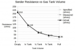
I am trying to correlate my fuel usage info from my Engine Gateways with actual fuel consumption (based on sender resistance), and cannot find any details about the actual resistance at specific levels, or any chart. The 240-33 ohm range is non-linear it seems. The best I found so far is only the usual points, 0, 1/4, 1/2, 3/4 and full. The change in difference is apparent between them. This is comparable to an radio volume control which has an "audio taper", but this taper is different (first 10% change = 50% resistance change, low to high). Does anyone have any further insight into sender ohms vs position?
Our last boat had a straight line from cap to tank bottom and my gas sticks were so easy.... Not an option any more!
I built a spreadsheet with 0.1" increments, determined the sender offset from top and bottom, then divided up the 20" travel of the sender (moeller reed type) equally over the range. What I found is that when the tank is low I "use" much more fuel (~50%), then when it's fuller. This became evident after filling the tanks at the midpoint of a trip over the weekend, only the 2nd fill of the season. The usage I was seeing before the fill was scary compared to the reported consumption! Post fill usage seems low compared to gateway reported usage.
My objective is to get a good handle on the reporting vs actual use, to calibrate the usage if needed, and rely on that going forward. Our Axiom MFD includes a Fuel Management tool, getting usage from engine gateways, and manual input of each fill. The gauges are quite inaccurate.
Speaking of gauges, is there such a thing as recalibrating SR gauges? The OP is pretty close, but tachs are significantly off (500rpm at 3800). The synchronizer and gateways agree, +/- 25rpm. The Temp gauges seem pretty close, but port runs about 170 (vs 160) higher when running 3800 rpm, according to the engine gateway, but stays at 160 on the gauge. I believe there are 2 senders, 1 to gauge and 1 to MEFI, so a difference may be related to where they are. Or not. Looks like both are in Thermostat housing, on opposing sides. Maybe just sender difference.