Pakmule
Member
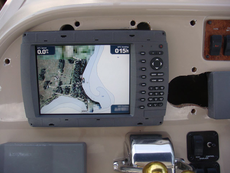
Yesterday I started the project of pulling the Raytheon RL70 from my 2000 310.
The first part was to pull the wiring harness which went fairly smoothly except the part where I put my multimeter on two wires to see if they were hot and promptly blew a 3.5 amp fuse in the foldout breaker box under the steering wheel.
Pulling out the unit itself was pretty straightforward as it just had a knurled knob at each corner. After pulling it out I had a big hole in my dash that is not even remotely big enough to hold the new Garmin unit
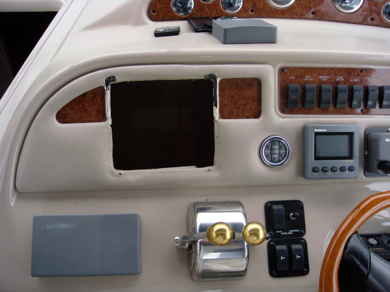
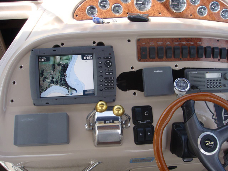
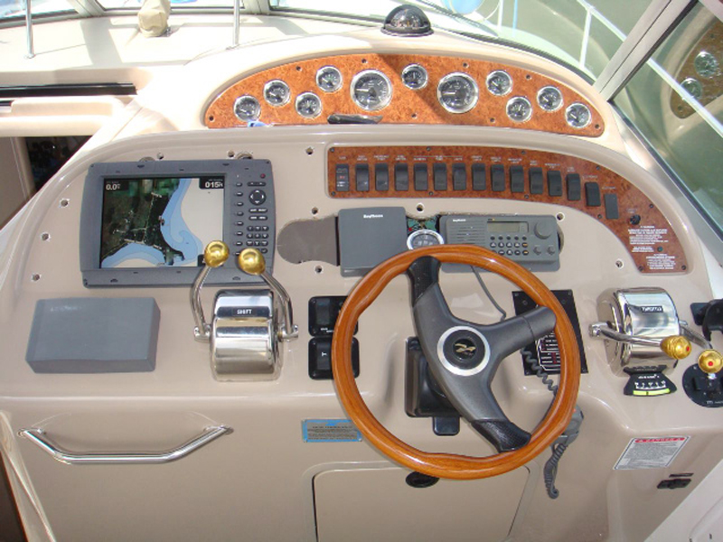
As the Garmin unit is much larger than the Raytheon I decided that I was going to end up cutting so much of the padded dash cover that it would probably just fall apart or be extremely difficult to stabilize. I am not a big fan of it anyway so I went ahead and completely removed it with the idea of laying something else down in it's place. Here is what I am left with after I removed the padded cover. Not pretty.
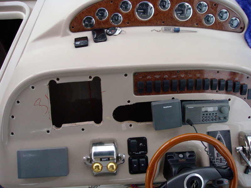
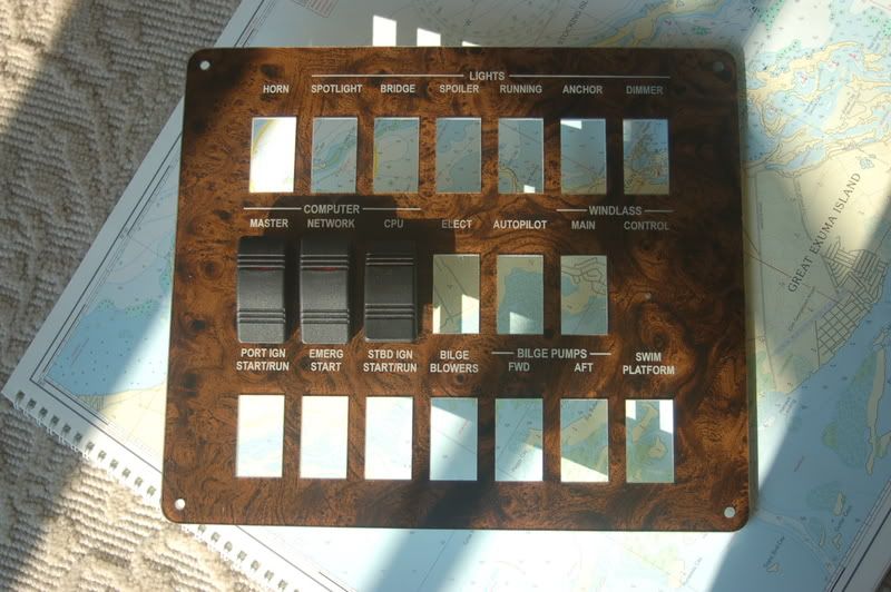
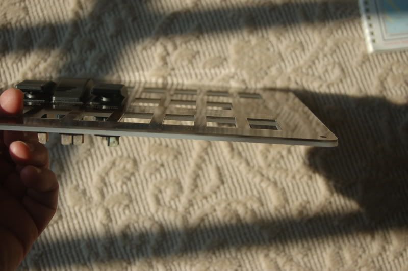
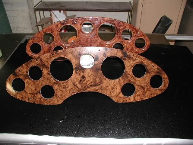
Here is the dash cover itself. I need to find something to replace it with that is sturdy enough to hold the GPS unit, stereo control, radio and depth finder readout.
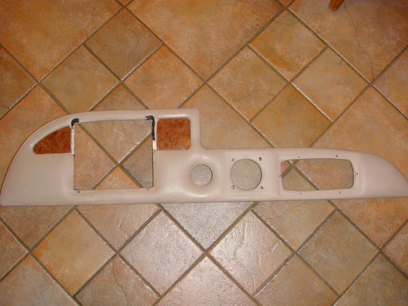
Any suggestions? I was thinking a piece of matching fiberglass or if I could find it, a piece of fiberglass that matches the other fake wood.
I will post more as I make headway.
The first part was to pull the wiring harness which went fairly smoothly except the part where I put my multimeter on two wires to see if they were hot and promptly blew a 3.5 amp fuse in the foldout breaker box under the steering wheel.
Pulling out the unit itself was pretty straightforward as it just had a knurled knob at each corner. After pulling it out I had a big hole in my dash that is not even remotely big enough to hold the new Garmin unit
As the Garmin unit is much larger than the Raytheon I decided that I was going to end up cutting so much of the padded dash cover that it would probably just fall apart or be extremely difficult to stabilize. I am not a big fan of it anyway so I went ahead and completely removed it with the idea of laying something else down in it's place. Here is what I am left with after I removed the padded cover. Not pretty.
Here is the dash cover itself. I need to find something to replace it with that is sturdy enough to hold the GPS unit, stereo control, radio and depth finder readout.
Any suggestions? I was thinking a piece of matching fiberglass or if I could find it, a piece of fiberglass that matches the other fake wood.
I will post more as I make headway.

") I placed the Garmin cutout sticker where I wanted the new device to go, cut out the center of the sticker where the old hole was and had at it. I followed the cut line on the sticker very closely and then had to go another 30 minutes of slightly massaging the hole as the bale mount knurling (if that is the right word) stuck out a bit and it was stopping the unit from sliding in. I ended up having to cut ear holes for that.
I placed the Garmin cutout sticker where I wanted the new device to go, cut out the center of the sticker where the old hole was and had at it. I followed the cut line on the sticker very closely and then had to go another 30 minutes of slightly massaging the hole as the bale mount knurling (if that is the right word) stuck out a bit and it was stopping the unit from sliding in. I ended up having to cut ear holes for that.