Dock Circuit Breaker Trips

Here is the markings on a marina style it’s a 15A but a 30 would have the same 30ma markings

1700501169221.jpeg
 
@Skybolt That's had me stumped! I've been confused as to how the breakers are all off and something that's "off" could be causing it to trip. Thanks so much for offering that explanation! I'll try to find the bus bar as well as I go through making the schematic.
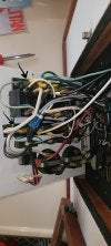
Ok so this just got more complicated, but a lot of information also has been brought up. The dock stanchion should be what @hughespat57 stated, and needs to be a 30ma GF trip.

To finish what I didn't say in my previous post, you will need to measure the resistance between the neutral an ground legs. With the power disconnected from the boat and the boat still switched to shore power. Measure the resistance between the neutral bus bar and the ground bus bar. There should be a virtual open between them. If there isn't try disconnecting the generator neutral and see what that measures.

Now if there isn't a problem when the power is connected to the boat and the main is on, with all of the breakers off and the pedestal doesn't trip then there isn't an issue with the neutral and ground. At that point, try turning on one breaker at a time and all of the appliances on that breaker. Then on to the next, possibly turning the previous one off.

The dock breaker needs to be fixed first, your old boat is not going to pass a 5ma reverse current breaker. Not to mention that breaker should not be on a dock stanchion.
 
Thanks! I'll be reaching out tomorrow to the dock's manager to see if they can get my breaker changed. Looks like https://superbreakers.com/products/siemens-qe130-30-amp would be what they should install.

Also to confirm (want to make sure I'm understanding everything properly :)
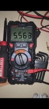
), I'll measure resistance and check if it's a virtual open (very high resistance) between the two labeled bars in below picture (while boat is disconnected from dock & shore power is switched to on). If there's not, then I'll disconnect generator neutral and remeasure resistance.
 

Attachments

  • 20231119_130344.jpg
    20231119_130344.jpg
    445.3 KB · Views: 35
Just went to the boat and did the above. When the shore power is set to on but all the switches are off, the resistance is over limit. As soon as I switch on the 30 AMP A/C main (the one in the video that makes the dock's circuit breaker trip) I start reading a resistance of 5.56MΩ.

It's pretty dark over here so I didn't do anything else but my plan is to disconnect the generator neutral next and see if that makes any change. If not, I'll start working through the circuits on the panel one at a time.
 

Attachments

  • 8a648305-56cf-4c5b-8a09-c41deebe2d6d.jpeg
    8a648305-56cf-4c5b-8a09-c41deebe2d6d.jpeg
    103.8 KB · Views: 21
Just went to the boat and did the above. When the shore power is set to on but all the switches are off, the resistance is over limit. As soon as I switch on the 30 AMP A/C main (the one in the video that makes the dock's circuit breaker trip) I start reading a resistance of 5.56MΩ.

It's pretty dark over here so I didn't do anything else but my plan is to disconnect the generator neutral next and see if that makes any change. If not, I'll start working through the circuits on the panel one at a time.

So your 5.5M ohm is fine. Ideally infinity is what you want, but usually unrealistic with these things.

Your main breaker switch's the ground and neutral lines and why the boat seems fine with it off. If you measured between the point(s) marked with arrows in your other pic, then the boat should be fine. If not, that's where you need to measure.

With all of the breakers off and then switching the main breaker on and the dock pops is an indication that the neutrals and grounds are connected somewhere. It is very difficult to follow the wires in your pic. White wires are going to the ground and neutral bar, hard to tell what is what. But if I had to guess on what's wrong, that 65vac part of the main breaker is tying the neutral and ground together. As a test you could lift the white wire from the ground and see if the main breaker can be turned on and not pop the breaker. Don't turn any of the other breakers on.

You may need to replace the main breaker with one that doesn't switch the grounds. All of the grounds should be tied together and not be switched.

EDIT: Your generator neutral and it's ground are tied together as per ABYC or should be. The shore/generator switch should lift the neutral of the generator when switched to shore.
 
Thanks for the tips! I did measure between those two arrows. I know earlier you mentioned disconnecting the generator neutral. Should I still try or is that not necessary with the measurement I made?
 
Thanks for the tips! I did measure between those two arrows. I know earlier you mentioned disconnecting the generator neutral. Should I still try or is that not necessary with the measurement I made?

If the 5.5M ohm reading was with the main breaker on, power disconnected from the boat, you should be fine.

But if I had to guess on what's wrong, that 65vac part of the main breaker is tying the neutral and ground together. As a test you could lift the white wire from the ground and see if the main breaker can be turned on and not pop the breaker. Don't turn any of the other breakers on.
 
Resistance between the Hot (black) and ground also needs to be measured with the circuit breakers off, the dock line connected to the boat but not connected to the dock power.
GFI devices measure the differential current between the Hot and Neutral legs. If the current on the Hot and Neutral conductors is not equal and the differential is greater than the GFI rating the GFI will trip.
A Hot leg leaking to ground can establish a differential like a neutral leaking to ground. Anything creating an imbalance in current between the Hot and Neutral will trip the GFI.

I suggested to measure with the main circuit breaker on, because I believe the issue is the main breaker and the piece that measures the 65v between ground and neutral. I have no practical experience with that type of breaker. But that may be what is causing the dock GFCI to pop when the main breaker is on. Much like having two gfci's on the same circuit. Just a guess at this point.
 
I suggested to measure with the main circuit breaker on, because I believe the issue is the main breaker and the piece that measures the 65v between ground and neutral. I have no practical experience with that type of breaker. But that may be what is causing the dock GFCI to pop when the main breaker is on. Much like having two gfci's on the same circuit. Just a guess at this point.
Wasn't that a different boat and thread on the 65V tripping device?
This boat is tripping the dock GFI.
Or did I miss something?
 
Wasn't that a different boat and thread on the 65V tripping device?
This boat is tripping the dock GFI.
Or did I miss something?

You may be right, but look at the pic of the panel, post #23. The ground and neutral are being switched by the main breaker, or at least it looks that way. To me, it looks like the same type of breaker, given the boats age. If not then I have no idea what type of breaker that is.
 
Hold on everyone stop!
Didn't we just have a thread with an older boat and the same setup?

This is a two pole breaker with the third section is a "shunt trip coil".
The coil is wired across Neutral and Ground intentionally.
It is an automatic circuit trip if there is a Reverse Polarity situation.

So this coil is wired just like the RP lamp.
But instead of illuminating it shuts off the main breaker (if RP)

This was a very old school design...
Like the lamp I would disconnect one side with the lamp and test again.
 
You may be right, but look at the pic of the panel, post #23. The ground and neutral are being switched by the main breaker, or at least it looks that way. To me, it looks like the same type of breaker, given the boats age. If not then I have no idea what type of breaker that is.
Hold on everyone stop!
Didn't we just have a thread with an older boat and the same setup?

This is a two pole breaker with the third section is a "shunt trip coil".
The coil is wired across Neutral and Ground intentionally.
It is an automatic circuit trip if there is a Reverse Polarity situation.

So this coil is wired just like the RP lamp.
But instead of illuminating it shuts off the main breaker (if RP)

This was a very old school design...
Like the lamp I would disconnect one side with the lamp and test again.
This was the image from the other thread -
1700573814650.png
 
Hi @hughespat57 I have labeled the RP lamp. Should I disconnect just the black (hot / #3 in my pic) wire and try what I did in the video to see if the dock's circuit breaker still trips?
 

Attachments

  • 20231119_130344.jpg
    20231119_130344.jpg
    450 KB · Views: 30
Hold on everyone stop!
Didn't we just have a thread with an older boat and the same setup?

This is a two pole breaker with the third section is a "shunt trip coil".
The coil is wired across Neutral and Ground intentionally.
It is an automatic circuit trip if there is a Reverse Polarity situation.

So this coil is wired just like the RP lamp.
But instead of illuminating it shuts off the main breaker (if RP)

This was a very old school design...
Like the lamp I would disconnect one side with the lamp and test again.

Worded better, but exactly what I was saying. And why I said lift the ground wire from the breaker.
 
Hi @hughespat57 I have labeled the RP lamp. Should I disconnect just the black (hot / #3 in my pic) wire and try what I did in the video to see if the dock's circuit breaker still trips?

Your not understanding what is going on. The issue is not with the hot leg, it is with the neutral and ground. As I mentioned a few post's up. Try disconnecting the white wire from the ground bus bar.
 
Hi @hughespat57 I have labeled the RP lamp. Should I disconnect just the black (hot) wire and try what I did in the video to see if the dock's circuit breaker still trips?
See attached.
The Class A GFCI is so sensitive at 5ma the coil and the RP lamp may be tripping the breaker.
It's not going to be a black where you need to disconnect to track down.
It's going to be lift a white Neutral or a Green Ground one by one to narrow the circuit.

What is odd for us all right now is that you have all the breakers off, and yet this is repeatable with just the main and the switch being cycled. That seems to indicate the issue may be before the branch circuits.


20231119_130344v2.jpg
 
Thanks! I should've known that it wouldn't be the black one o_O Appreciate the help! I'll do what both of you all have said in a little bit and report back.
 
If that is indeed a Shunt Trip device then remove the white wire as shown and see if the dock GFCI continues to trip.
shunttrip.jpg
 
If that is indeed a Shunt Trip device then remove the white wire as shown and see if the dock GFCI continues to trip.
View attachment 154536
Almost same, but I would remove the green at the block, just because its easy and that will remove the coil AND the pilot light for RP.
He has a combined power and RP lamp assembly so the lamp would still be in play since it has its own White.
 

Forum statistics

Threads
113,218
Messages
1,428,820
Members
61,115
Latest member
Gardnersf
Back
Top