

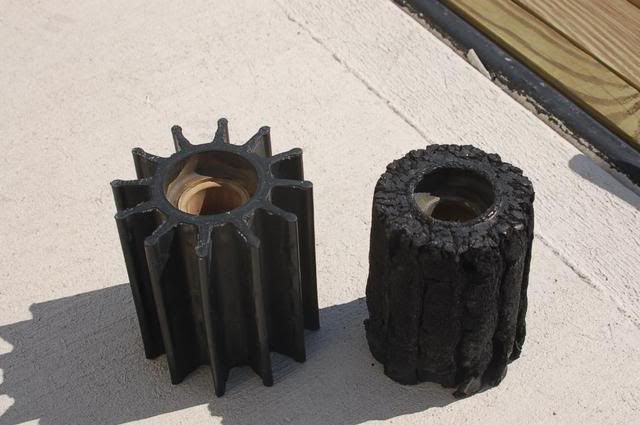
I have 250 degree temp sensors on the exhaust pipes on my QSM-11 diesels. The idea here is that when the pipe gets that hot, the raw water cooling must have stopped. Well... as some of you recall I forgot to open a seacock last year and ended up with this damage to the impeller:
The temp sensor on the starboard engine did not register a fault and warn me via the Sea Ray Systems monitor as it should have. Granted I didn't overheat the engines and caught it when the coolant temp went up just 10 degrees over normal so maybe if I would have let it overheat more it would have gone off...
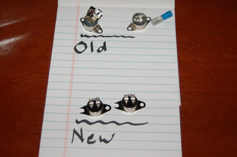
Additionally, the old one on the port exhaust has been bumped a few times and the connectors broke off. I ended up ordering new ones from the exhaust company in Florida but got 220 degree ones instead of the OEM 250 degree ones. Here's a picture of the old and new ones:
Note the broken off spade connectors on one of the old ones. Here's a close up of one of the new ones:
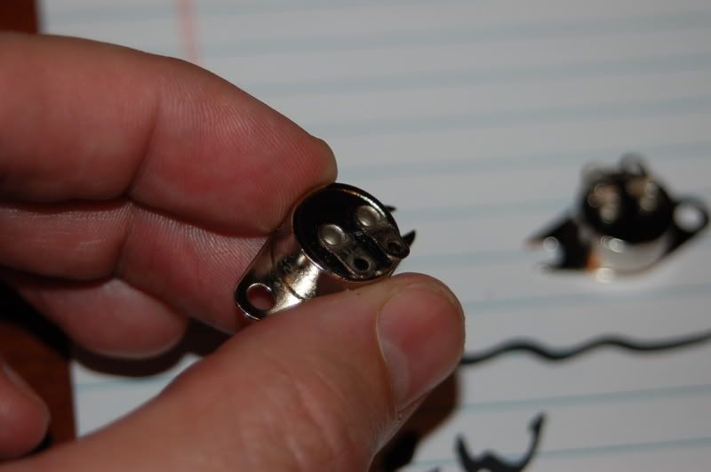
My question is this... How does one go about hooking the two wires to those small spades? The old ones appeared to have some of the bigger spades welded on the smaller ones so a female spade connector could be used... Any ideas? Mr. Crimp Man? You out there?
The temp sensor on the starboard engine did not register a fault and warn me via the Sea Ray Systems monitor as it should have. Granted I didn't overheat the engines and caught it when the coolant temp went up just 10 degrees over normal so maybe if I would have let it overheat more it would have gone off...
Additionally, the old one on the port exhaust has been bumped a few times and the connectors broke off. I ended up ordering new ones from the exhaust company in Florida but got 220 degree ones instead of the OEM 250 degree ones. Here's a picture of the old and new ones:
Note the broken off spade connectors on one of the old ones. Here's a close up of one of the new ones:
My question is this... How does one go about hooking the two wires to those small spades? The old ones appeared to have some of the bigger spades welded on the smaller ones so a female spade connector could be used... Any ideas? Mr. Crimp Man? You out there?

